Electrical Power Management
This article explains how to power on the CanSat NeXT board, how to safely connect external devices to the board, and finally how the power system works.
Getting Started
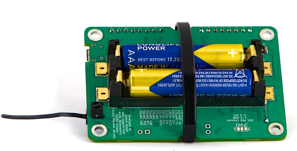
For most users, it is often enough to simply add two AAA-batteries to the on-board battery holder and secure them in place. When the USB is connected, CanSat NeXT automatically switches to use the USB power instead of the batteries, so that the battery life is extended. Remember to switch to fresh batteries before a flight.
CanSat NeXT Power System
There are three ways to power the CanSat NeXT. The default way is to power it with USB, so that when the user is developing the software, the PC powers the device and no external power is required. Second way is to use the on-board batteries (OBB). This is done by inserting two standard 1.5 V AAA batteries into the battery connector on the bottom side of the main board. The USB is still the default way even if batteries are inserted, i.e. the battery capacity is not used when USB is plugged in.
These are the usual options, and should cover most use cases. Additionally, however, there are two “advanced” options for powering CanSat NeXT if needed for a special purpose. First, the board has empty through-hole headers labeled EXT, that can be used for connecting an external battery. The battery voltage can be 3.2-6V. The EXT line is automatically disconnected when USB is not present to extend battery life and to protect the battery. There is a safety feature that the OBB is disabled if a battery is connected, but the OBB should still not be present when external batteries are used.
There is also one last option that gives all responsibility to the user, and that is inputting 3V3 to the device through the extension interface. This is not a safe way to power the device, but advanced users who know what they are doing might find this the easiest way to achieve the desired functionalities.
In summary, there are three safe ways to power CanSat NeXT:
- Using USB - main method used for development
- Using on-board batteries - recommended method for flight
- Using an external battery - For advanced users
Using regular AAA batteries, a battery life of 4 hours was reached in room temperature, and 50 minutes in -40 degrees celsius. During the test, the device read all the sensors and transmitted their data 10 times per second. It should be noted that regular alkaline batteries are not designed to work in such low temperatures, and they usually start leaking potassium after this kind of torture tests. This is not dangerous, but the alkaline batteries should be always disposed of safely afterwards, especially if they were used in an uncommon environment such as extreme cold, or having been dropped from a rocket. Or both.
When using USB, the current draw from the extension pins should not exceed 300 mA. The OBB are slightly more forgiving, giving at most 800 mA from the extension pins. If more power is required, an external battery should be considered. This is most likely not the case unless you are running motors (small servos are fine) or heaters, for example. Small cameras etc. are still fine.
Extra - how the adaptive multi-source power scheme works
To achieve the desired functionalities safely, we need to consider quite many things in the power system design. First, to safely be able to connect USB, EXT and OBB at the same time, the power system needs to switch on and off the various power sources. This is further complicated by the fact that it can’t be done in software, as the user needs to be able to have any software they desire without endangering safe operations. Furthermore, the OBB has a quite different voltage range to the USB and external battery. This necessitates the OBB to use a boost regulator, while the USB and EXT need either a buck regulator or an LDO. For simplicity and reliability, an LDO is used in that line. Finally, one power switch should be able to disconnect all of the power sources.
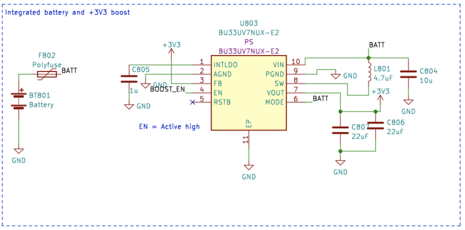
Below is the schematic for the boost converter. The IC is BU33UV7NUX, a boost converter specifically designed to give +3.3V from two alkaline batteries. It is enabled when the BOOST_EN line is high, or above 0.6 V.
All OBB, USB and EXT lines are protected with a fuse, over-current protection, reverse-voltage and current protection and over temperature protection. Furthermore, the OBB is protected with under voltage lock out and short circuit protection, as those situations should be avoided with alkaline batteries.
Note in the following section, that external battery voltage is V_EXT, USB voltage is VBUS and OBB voltage is BATT.
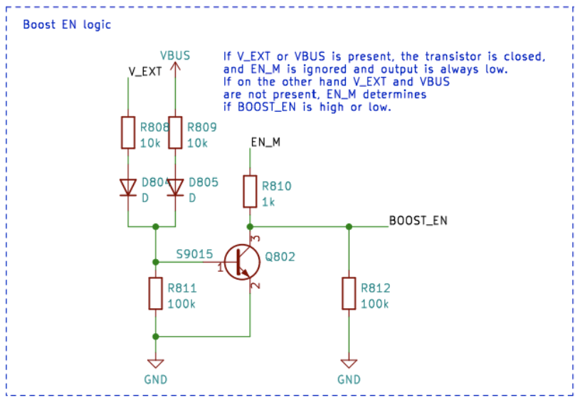
The BOOST_EN line is controlled by a switch circuit, which either takes the input from EN_MASTER (EN_M) line, or ignores that if V_EXT or VBUS is present. This is made to ensure that the boost is always off when VBUS and V_EXT is present, and it is only enabled if both VBUS and V_EXT are at 0V and the EN_M is high.
Or as a truth table:
| V_EXT | VBUS | EN_M | BOOST_EN |
|---|---|---|---|
| 1 | 1 | 1 | 0 |
| 1 | 1 | 0 | 0 |
| 0 | 0 | 0 | 0 |
| 0 | 0 | 1 | 1 |
So BOOST_EN = EN_M ∧ !(V_EXT ∨ V_BUS).
Next, we need to disconnect V_EXT if VBUS is present to prevent undesired discharge or accidental charging. This is done using a power switch IC with help of a transistor circuit which takes the enable-line of the power switch down if VBUS is present. This disconnects the battery. The USB line is always used when present, so it is routed to the LDO with a simple schottky diode.
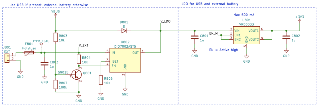
Overall, this circuit leads to a functionality where USB power is used if present, and V_EXT used when USB is not present. Finally, the EN_M is used to enable or disable the LDO.
The EN_M is controlled by the user through a power switch. The switch connects EN_M to either USB or EXT, or the battery voltage when only OBB is used. When the switch is turned off, it connects EN_M to ground, turning off both the LDO and the boost regulator.
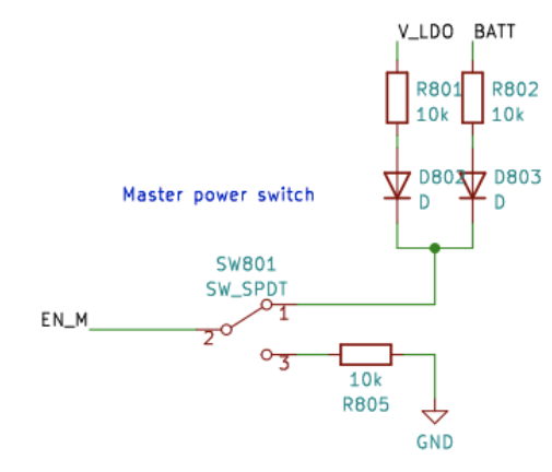
So in practice, the power switch turns the device on/off, USB is used if present, and V_EXT is preferred over OBB. Finally, there is one more detail to consider. What voltage should ESP32 measure as the battery voltage?
This was solved in a simple way. The voltage connected to the ESP32 ADC is always the OBB, but the user can select V_EXT instead by cutting the jumper with a scalpel and soldering the jumper JP801 to short 2-3 instead. This selects V_EXT to the BATT_MEAS instead.
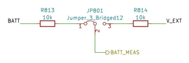
The jumper can be found from the bottom side of the CanSat NeXT main board. The jumper is quite easy to solder, so don’t be afraid to cut the 1-2 line if you are using an external battery. It can always be resoldered to again use 1-2 instead.