Lesson 11: Satellite Must Grow
While the CanSat NeXT already has many integrated sensors and devices on the satellite board itself, many exciting CanSat missions require the use of other external sensors, servos, cameras, motors, or other actuators and devices. This lesson is slightly different to the previous ones, as we'll discuss the integration of various external devices to CanSat. Your actual use case is probably not considered, but perhaps something similar is. However, if there is something you feel should be covered here, please do send feedback to me at samuli@kitsat.fi.
This lesson is slightly different to the previous, as while all information is useful, you should feel free to jump to the areas that are relevant to your project specifically, and use this page as a reference. However, before continuing this lesson, please look through the materials presented in the hardware section of CanSat NeXT documentation, as it covers a lot of information required for integrating external devices.
Connecting external devices
There are two great ways to connect external devices to the CanSat NeXT: Using Perf Boards and custom PCBs. Making your own PCB is easier (and cheaper) than you might think, and to get started with them, a good starting point is this KiCAD tutorial. We also have a template available for KiCAD, so that making your boards to the same format is very easy.
That being said, for most CanSat missions soldering the external sensors or other devices to a perf board is a great way to create reliable, sturdy electronics stacks.
An even easier way to get started, especially when first prototyping, is to use jumper cables (Also called Dupont cables or breadboard wire). They are typically even provided with the sensor breakouts, but can also be bought separately. These share the same 0.1 inch pitch used by the extension pin header, which makes connecting devices with cables very easy. However, although cables are easy to use, they are rather bulky and unreliable. For this reason, avoiding cables for the flight model of your CanSat is warmly recommended.
Sharing power to the devices
CanSat NeXT uses 3.3 volts for all of its own devices, which is why it is the only voltage line provided to the extension header as well. Many commercial breakouts, especially older ones, support also 5 volt operation, as that is the voltage used by legacy Arduinos. However, the vast majority of devices also support operation directly through 3.3 volts.
For the few cases where 5 volts is absolutely required, you can include a boost converter on the board. There are ready made modules available, but you can also directly solder a lot of devices to the perf board. That being said, do try to first use the device from 3.3 volts instead, as there is a good chance it will work.
The maximum recommended current draw from the 3.3 volt line is 300 mA, so for current-hungry devices such as motors or heaters, consider an external power source.
Data lines
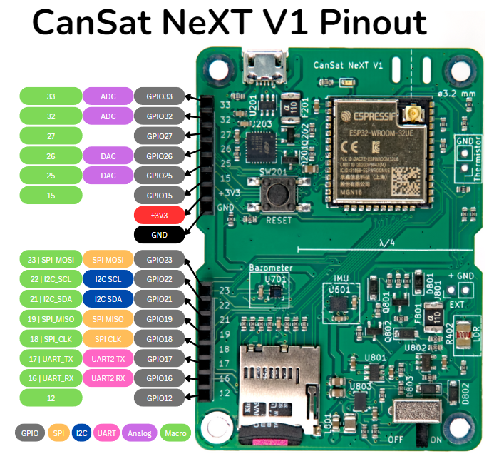
The extension header a total of 16 pins, out of which two are reserved for ground and power lines. The rest are different types of inputs and outputs, most of which have multiple possible uses. The board pinout shows what each of the pins can do.
GPIO
All of the exposed pins can be used as general purpose inputs and outputs (GPIO), which means that you can perform digitalWrite and digitalRead functions with them in the code.
ADC
Pins 33 and 32 have an analog to digital converter (ADC), which means that you can use analogRead (and adcToVoltage) to read the voltage on this pin.
DAC
These pins can be used with to create a specific voltage on the output. Note that they do produce the desired voltage, however they can only provide a very small amount of current. These could be used as reference points for sensors, or even as an audio output, however you'll need an amplifier (or two). You can use dacWrite to write the voltage. The is also an example in the CanSat libary for this.
SPI
Serial Peripheral Interface (SPI) is a standard dataline, often used by Arduino breakouts and similar devices. An SPI device needs four pins:
| Pin Name | Description | Usage |
|---|---|---|
| MOSI | Main Out Secondary In | Data sent from the main device (e.g., CanSat) to the secondary device. |
| MISO | Main In Secondary Out | Data sent from the secondary device back to the main device. |
| SCK | Serial Clock | Clock signal generated by the main device to synchronize communication. |
| SS/CS | Secondary Select/Chip Select | Used by the main device to select which secondary device to communicate with. |
Here main is the CanSat NeXT board, and secondary is whatever device you want to communicate with. The MOSI, MISO and SCK pins can be shared by multiple secondaries, however all of them need their own CS pin. The CS pin can be any GPIO pin, which is why there isn't a dedicated one in the bus.
(Note: Legacy materials sometimes use the terms "master" and "slave" to refer to the main and secondary devices. These terms are now considered outdated.)
On the CanSat NeXT board, the SD card uses the same SPI line as the extension header. When connecting another SPI device to the bus, this doesn't matter. However, if the SPI pins are used as GPIO, the SD card is effectively disabled.
To use SPI, you often need to specify which pins from the processor are used. One example could be like this, where macros included in the CanSat library are used to set the other pins, and the pin 12 is set as chip select.
adc.begin(SPI_CLK, SPI_MOSI, SPI_MISO, 12);
The macros SPI_CLK, SPI_MOSI, and SPI_MISO are replaced by the compiler with 18, 23, and 19, respectively.
I2C
Inter-Integrated Circuit is another popular data bus protocol, especially used for small integrated sensors, such as the pressure sensor and IMU on the CanSat NeXT board.
I2C is handy in that it only requires two pins, SCL and SDA. There is also no separate chip select pin, but instead different devices are separated by different addresses, which are used to establish communication. This way, you can have multiple devices on the same bus, as long as they all have an unique address.
| Pin Name | Description | Usage |
|---|---|---|
| SDA | Serial Data Line | Bi-directional data line used for communication between main and secondary devices. |
| SCL | Serial Clock Line | Clock signal generated by the main device to synchronize data transfer with secondary devices. |
The barometer and IMU are on the same I2C bus as the extension header. Check the addresses of those devices at the page On-Board sensors. Similar to SPI, you can use these pins for connecting other I2C devices, but if they are used as GPIO pins, the IMU and barometer are disabled.
In Arduino programming, I2C is sometimes called Wire. Unlike SPI, where the pinout is often specified for each sensor, I2C is often used in Arduino by first establishing a data line, and then referencing that for each sensor. Below is an example of how the barometer is initialized by the CanSat NeXT library:
Wire.begin(I2C_SDA, I2C_SCL);
initBaro(&Wire)
So, first a Wire is initialized by telling it the right I2C pins. The macros I2C_SDA and I2C_SCL set in the CanSat NeXT library are replaced by the compiler with 22 and 21, respectively.
UART
Universal asynchronous receiver-transmitter (UART) is in some ways the simplest data protocol, as it simply sends the data as binary at a specified frequency. As such, it is limited to point-to-point communication, which means that you usually cannot have multiple devices on the same bus.
| Pin Name | Description | Usage |
|---|---|---|
| TX | Transmit | Sends data from the main device to the secondary device. |
| RX | Receive | Receives data from the secondary device to the main device. |
On CanSat, the UART in the extension header is not used for anything else. There is another UART line however, but it is used for the USB communication between satellite and a computer. This is what is used when sending data to the Serial.
The other UART line can be initialized in code like this:
Serial2.begin(115200, SERIAL_8N1, 16, 17);
PWM
Some devices also use pulse-width modulation (PWM) as their control input. It can also be used for dimmable LEDs or controlling power output in some situations, among many other use cases.
With Arduino, only certain pins can be used as PWM. However, as CanSat NeXT is an ESP32 based device, all of the output pins can be used to create a PWM output. The PWM is controlled with analogWrite.
What about (my specific use case)?
For most devices, you can find a lot of information from internet. For instance, google the specific breakout that you have, and use these documents to modify the examples you find for use with CanSat NeXT. Also, the sensors and other devices have datasheets, which should have a lot of information about how to use the device, although they can be bit tricky to decypher sometimes. If you feel there is something this page should have covered, please do let me know at samuli@kitsat.fi.
In the next, final lesson, we'll discuss how to prepare your satellite for the launch.