Lesson 4: Resistance isn't Futile
So far we have focused on using digital sensor devices to get values directly in SI units. However, electrical devices make the measurement usually in an indirect way, and the conversion to the desired units is then done afterwards. This was done previously by the sensor devices themselves (and by the CanSat NeXT library), but many sensors we use are much more simple. One type of analogue sensors is resistive sensors, where the resistance of a sensor element changes depending on some phenomena. Resistive sensors exist for a multitude of quantities - including force, temperature, light intensity, chemical concentrations, pH, and many others.
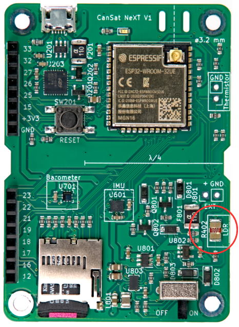
In this lesson, we will be using the light-dependant resistor (LDR) on the CanSat NeXT board to measure surrounding light intensity. While the themistor is used in a very similar way, that will be the focus of a future lesson. The same skills apply directly to using the LDR and thermistor, as well as many other resistive sensors.
Physics of Resistive Sensors
Instead of jumping directly to the software, let's take a step back and discuss how reading a resistive sensor generally works. Consider the schematic below. The voltage at LDR_EN is 3.3 volts (operating voltage of the processor), and we have two resistors connected in series on its path. One of these is the LDR (R402), while the other one is a reference resistor (R402). The resistance of the reference resistor is 10 kilo-ohms, while the resistance of the LDR varies between 5-300 kilo-ohms depending on the light conditions.

Since the resistors are connected in series, the total resistance is
and the current through the resistors is
where is the operational voltage of the MCU. Remember that the current has to be the same through both of the of the resistors. Therefore we can calculate the voltage drop over the LDR as
And this voltage drop is the voltage of the LDR that we can measure with an analog-to-digital converter. Usually this voltage can be directly correlated or calibrated to correspond to measured values, like for example from voltage to temperature or brightness. However, sometimes it is desirable to first calculate the measured resistance. If necessary, it can be calculated as:
Reading the LDR in Practice
Reading the LDR or other resistive sensors is very easy, as we just need to query the analog-to-digital converter for the voltage. Let's start this time a new Arduino Sketch from scratch. File -> New Sketch.
First, let's start the sketch like before by including the library. This is done at the beginning of the sketch. In the setup, start the serial and initialize CanSat, just like before.
#include "CanSatNeXT.h"

void setup() {
  Serial.begin(115200);
  CanSatInit();
}
A basic loop to read the LDR isn't much more complicated. The resistors R401 and R402 are already on the board, and we just need to read the voltage from their common node. Let's read the ADC value and print it.
void loop() {
    int value = analogRead(LDR);
    Serial.print("LDR value:");
    Serial.println(value);
    delay(200);
}
With this program, the values clearly react to lighting conditions. We get lower values when the LDR is exposed to light, and higher values when it is darker. However, the values are in hundreds and thousands, not in an expected voltage range. This is because we are now reading the direct output of the ADC. Each bit represent a voltage comparison ladder being one or zero depending on the voltage. The values are now 0-4095 (2^12-1) depending on the input voltage. Again, this direct measurement is probably what you want to use if you are doing something like detecting pulses with the LDR, but quite often regular volts are nice to work with. While calculating the voltage yourself is a good exercise, the library includes a conversion function that also considers the non-linearity of the ADC, meaning that the output is more accurate than from a simple linear conversion.
void loop() {
    float LDR_voltage = analogReadVoltage(LDR);
    Serial.print("LDR value:");
    Serial.println(LDR_voltage);
    delay(200);
}
This code is compatible with the serial plotter in Arduino Code. Try it out!
It could be useful to detect the CanSat having been deployed from the rocket, so that for instance the parachute could be deployed at the right time. Can you write a program that detects a simulated deployment? Simulate the launch by first covering the LDR (rocket integration) and then uncovering it (deployment). The program could output the deployment to the terminal, or blink an LED to show that the deployment happened.
The next lesson is about using the SD-card to store measurements, settings, and more!